7 Pin Trailer Plug Wiring Diagram
Make sure these have not inadvertently been swapped. 12 pin flat this is an extension of the 7 pin flat.
[DIAGRAM] Wiring Diagram Of A 7 Pin Trailer Plug Wiring Diagram FULL Version HD Quality Wiring
The 7 pin flat plug will fit into a 12 pin flat socket and work perfectly.

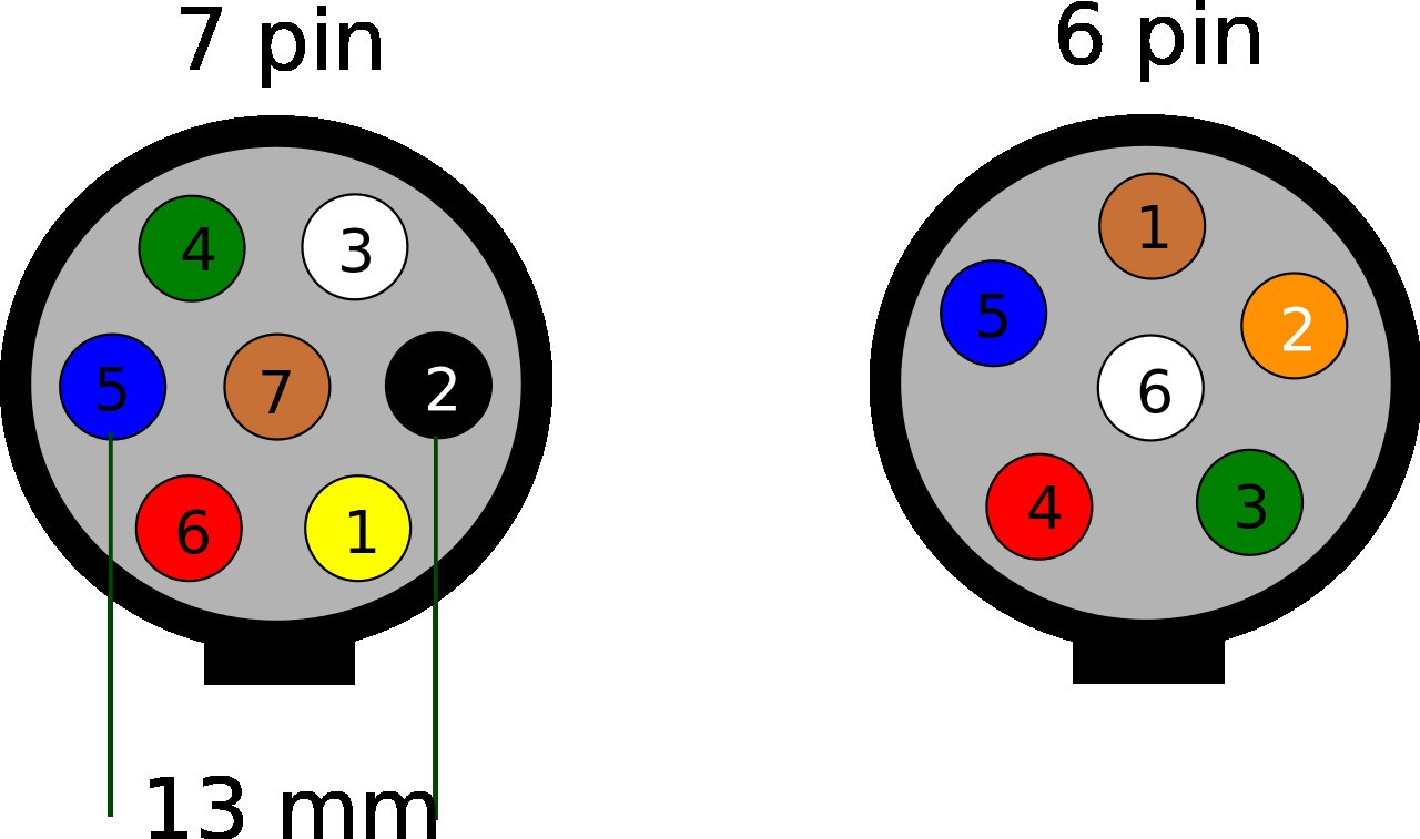
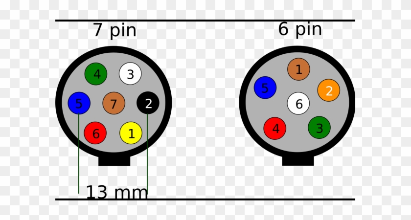
7 pin trailer plug wiring diagram. Australian trailer plug and socket wiring diagrams. 7 way trailer wiring diagram is explained in details in the picture and the table below: All diagrams are as viewed from the cable side.
If not, the arrangement won’t work as it should be. The wiring diagram is normally utilized in electrical design to plan the placement of electric. Yellow pin for abandoned brake light and left handed markers.
7 pin ‘n’ type trailer plug wiring diagram7 pin trailer wiring diagramthe 7 pin n type plug and socket is still the most common connector for towing. 7 wire trailer connector wiring diagram. Click on the image below to enlarge it.
Blue pin for electric brakes. Use the 7 pin connector anyway see below and just leave out the last 2 wires. This car is designed not only to travel 1 location.
As a professional rv transporter i have seen to many trucks wired with those 2 wires to small and cause a fire from overheating. Narva 7 and 12 pin trailer connectors comply with all relevant adrs. If your truck has a built in 7 pin socket but you only need 5 of the pins.
Click on the image below to enlarge it. 7 pin flat the best! Furthermore, wiring diagram gives you enough time frame by which the tasks are to be completed.
Injunction of two wires is usually indicated by black dot on the junction of 2 lines. It is very easy to attract a wiring diagram; You just require to have a excellent comprehension on different kinds of wiring and their objectives.
The first diagram is a simple set up of two brake lights, two indicators and two side lights. Wiring diagram of a 7 pin trailer plug. You simply require to have a excellent understanding on various types of wiring and their purposes.
You may be capable to understand precisely when the projects should be finished, that makes it easier for you personally to effectively control your time and. In the trailer wiring diagram and connector application chart below use the first 5 pins and ignore the rest. The table and diagram below explains the connections used on.
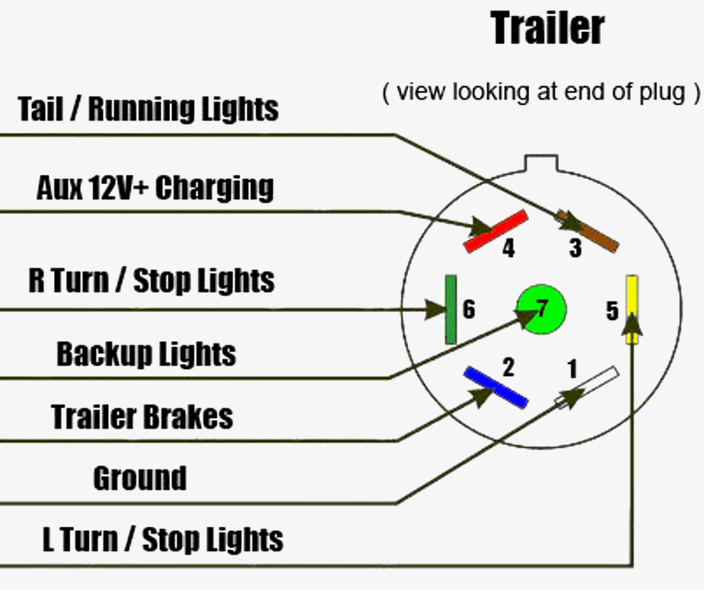
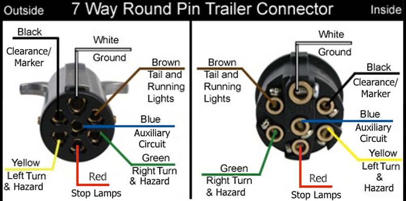
It shows the parts of the circuit as simplified shapes, as well as the power. This is what the 7 pin round trailer plug looks like: As stated earlier, the lines in a 7 pin trailer wiring diagram with brakes signifies wires.
800 x 600 px, source: Green pin yellow pin for appropriate brake light and turn mark. The 7 pin round plug on the trailer has individual female sockets for the each pins.
The second diagram shows two brake lights, two indicators, two side lights and a fog light. Each component should be set and connected with other parts in specific way. All diagrams are as viewed from the cable side.
Small 7 pin round (qld) identifying: Wiring plug diagram created date. 7 pin plug wiring diagram by vallery masson on june 17, 2021 a wiring diagram is a type of schematic which utilizes abstract pictorial signs to show all the affiliations of parts in a system.
But, it doesn’t mean link between the cables. Red 12 volt auxiliary power. Below is a diagram for the original plug and socket showing the functions of each pin.
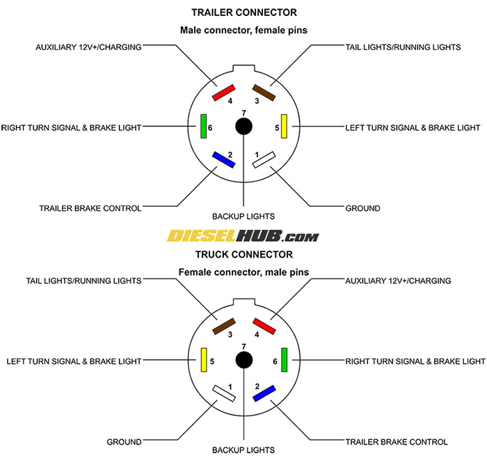
Here are two wiring diagrams for the 7 pin ‘n’ type trailer electrical plug. Wiring diagram trailer plugs and sockets. White pin to your floor.
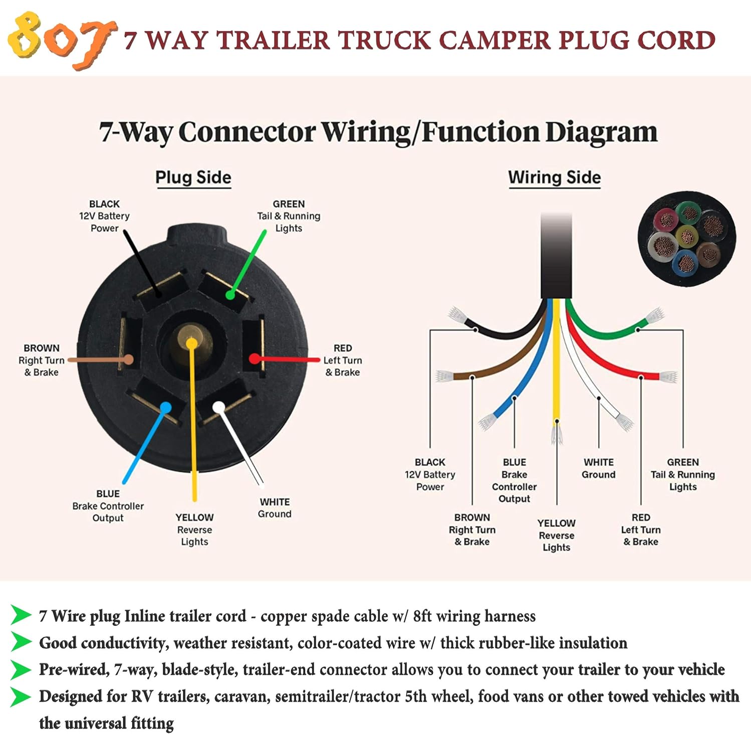
7 way trailer wiring diagram is explained in details in the picture and the table below: 11/10 for 2011 wiring diagrams note: Brown pin for unwanted markers, tail lights, and running lights.
It is very easy to draw a wiring diagram; In some cases and more often in europe the trailer light will be connected using a 13 pin plug and socket. There will be primary lines which are represented by l1, l2, l3, and so on.
The first diagram is a simple set up of two brake lights. 7 way plug wiring diagram standard wiring* post purpose wire color tm park light green (+) battery feed black rt right turn/brake light brown lt left turn/brake light red s trailer electric brakes blue gd ground white a accessory yellow this is the most common (standard) wiring scheme for rv plugs and the one used by major auto manufacturers today. Sometimes, the cables will cross.
[DIAGRAM] 7 Pin Rv Trailer Connector Wiring Diagram FULL Version HD Quality Wiring Diagram

7 Pin Trailer Plug Wiring Diagram Database Wiring Diagram Sample
Heavy Duty 7 Way Trailer Plug Wiring Diagram just wiring

7 Pin Trailer Wiring Diagram Uk Collection
Trailer Wiring Diagram Australia 7 Pin Flat Trailer Wiring Diagram

Ford 7 Pin Trailer Wiring Diagram Free Wiring Diagram

7 Pin Rv Trailer Plug Wiring Diagram Trailer Wiring Diagram

7Pin connector in bed... DEAD? Ford Truck Enthusiasts Forums
Wiring Diagram For 7 Pin Trailer Connector Trailer Wiring Diagram

Trailer Plug 7 Pin Wiring Diagram Trailer Wiring Diagram

7 Pin Round Trailer Connector Wiring Diagram Trailer Wiring Diagram

Trailer 7 Way Plug Wiring Diagram Trailer Wiring Diagram

7 Pin Trailer Connector Diagram 6 Prong Trailer Wiring Diagram Wiring Diagram And

Wiring Diagram for the Pollak HeavyDuty, 7Pole, Round Pin, Trailer Wiring Connector PK11700
Wiring Diagram For 7 Prong Trailer Plug Trailer Wiring Diagram

Trailer Connector Pinout Diagrams 4, 6, & 7 Pin Connectors
2003 Dodge Ram 7 Pin Trailer Wiring Diagram Images Wiring Collection

Trailer Wiring Diagram 7 Pin Round South Africa Trailer Wiring Diagram

Trailer Wiring Diagram 7 Pin Round Wiring Diagram