Heat Pump Thermostat Wiring Explained
Before uninstalling the old thermostat take a picture of the wiring with your cell phone before removing the. Thermostat wiring color code r, rh & rc terminals.
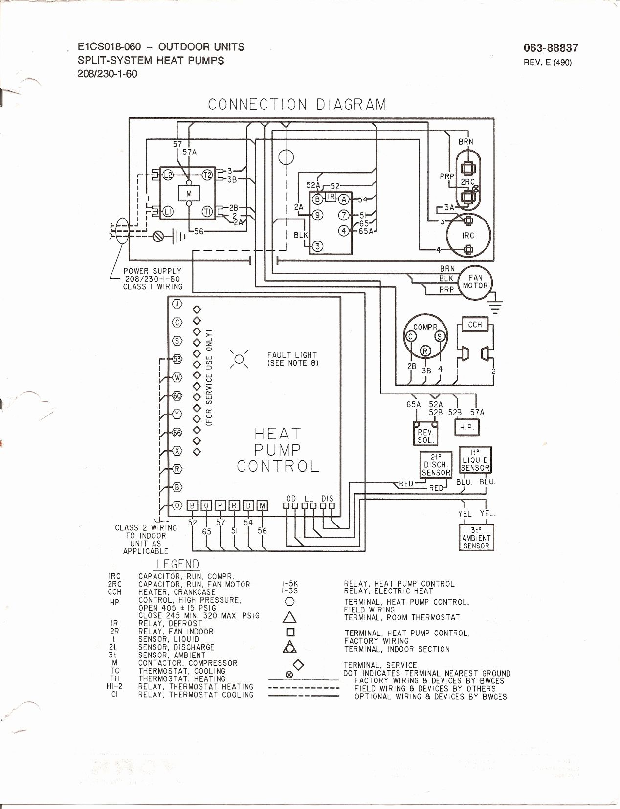
[LN_0502] Heat Pump Wiring Explained Download Diagram

Thermostat red wire (r, rh, and rc) this wire is present in all thermostats and is used to power your hvac system.

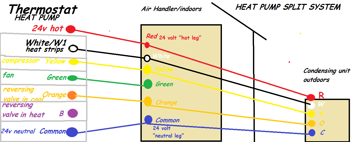
Heat pump thermostat wiring explained. In a heat pump, this is for the backup heat source. O wire shift the reversing valve from heating to cooling while the b wire does the opposite (cooling to heating). It connects directly to the furnace, boiler or other.
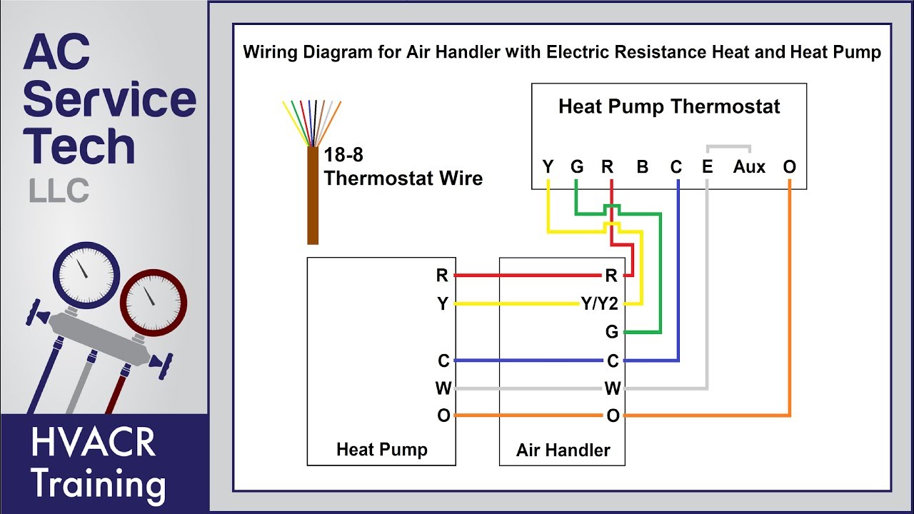
The y wire is yellow and connects to your air conditioning compressor. Air handler, heat pump, electric resistance. For all other systems, the wire connects to a transformer at the other end.
If not, the arrangement won’t work as it should be. This wire will also run to the air handler/furnace and the condenser. The w terminal the one that triggers the heating.
Heat pump thermostat wiring chart. Up to 20% cash back the white wire connects the heat source to the w terminal, the yellow wire connects the air conditioner to the y terminal, and the green wire connects the fan to the g terminal. The defrost control board in the.
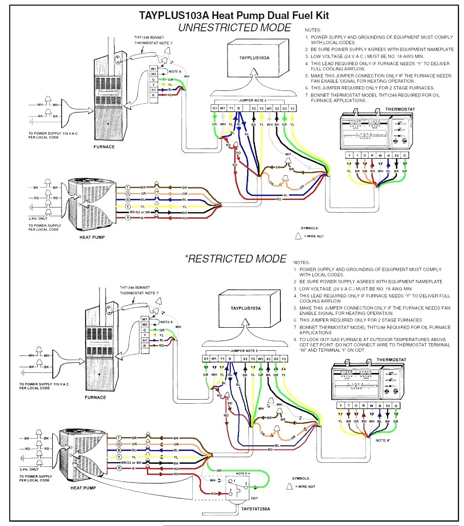
Goodman phk024 1f wiring diagrams in 2021 thermostat wiring. Mp3 ميل, understanding and wiring heat pump thermostats with aux & em. If your thermostat controls your heat, you will have a white wire.
Heat pump thermostat wiring explained mp3, heat pump thermostat wiring explained! A heat pump is part of a heating and cooling system and is installed outside your home. C is known as the common terminal.
Each component ought to be set and linked to different parts in specific way. Goodman heat pump wiring diagram wiring diagrams hubs goodman heat pump wiring diagram the diagram provides visual representation of a electric structure. Air handler, heat pump, electric resistance.
In the most basic system, this functionality is provided by use of a fan center relay, and the low voltage wiring to the thermostat now will require a minimum of three wires (for heat only units) and four wires (for heat / cool / fan) for control. One is for cool and the other is for heat, hence the abbreviation “rh” and “rc”. The g wire is green and connects to the fan.
The red wire is usually the 24 vac power wire, which begins at the transformer. R red is hot 24 volts, o orange reversing valve, w white is heat thanks. Colors, terminals, functions, circuit path!
The optional common wire connects to the c terminal to complete the circuit between transformer and thermostat, providing the thermostat with operating power. The color of wire r is usually red and c is black. It runs to the r,.
The basic heat pump wiring for a heat pump thermostat is illustrated here. 1 heat / 1 cool thermostat. It corresponds to the chart below to explain the thermostat terminal functions.
It corresponds with the chart (ruud and rheem, reversing valve powered in heating mode) 1 heat / 1 cool thermostat. These two connections will ensure that there is power to the thermostat that you are.
Whether it is electric heat strips or a gas furnace (dual fuel), the w terminal controls this. You can run 18:10 thermostat wire which gives you additional wires for a potential outdoor sensor. In cooler months, a heat pump pulls heat from the cold outdoor air and transfers it indoors, and in warmer months, it pulls heat out of indoor air to cool your home.
Air handler, ac separated from furnace, rc and r jumper removed. Goodman heat pump thermostat wiring diagram to honeywell 5000 8 wire goodman heat pump thermostat wiring diagram. It is typically found in a heat pump or ventilation.
Y yellow is compressor, g green for fan. Like an air conditioner, it can cool your home, but it’s also capable of providing heat. Here i am telling what each terminal if for.
A 220v/110v (depending on your country) system connects the power source directly to the heating device (a furnace usually). When it comes to the honeywell thermostat wiring heat pump, you are wiring the heat pump thermostat over to the indoor wire handler you going to typically run 18:8 thermostat wires. As shown in the diagram, you will need to power up the thermostat and the 24v ac power is connected to the r and c terminals.
Your heat pump uses o and b wire. A look at thermostats and climate control within the home for heating, air conditioning, fan auto/on, terminal labels, wires needed and more. The o and b wires are easy enough to spot because they are ‘orange’ and ‘dark blue,’ respectively.
(reversing valve powered in cooling mode, color coded) heat pump thermostat.
White Rodgers Thermostat Wiring Diagram Heat Pump White
120V Thermostat Wiring Diagram Simple Nuheat Wiring

Indepth Thermostat Wiring Guide For Homeowners

Goodman Air Handler To Heat Pump Wiring Diagram Wiring
Heat Pump Thermostat Wiring Explained! Colors, Terminals
Thermostat Heat Pump Wiring Identify A Thermostat Wire

Rheem Heat Pump Thermostat Wiring Diagram Wiring Diagram

[ZT_6141] Heat Pump Wiring Explained Wiring Diagram

Thermostat Wiring Diagram With Heat Pump Doctor Heck

Rheem Heat Pump Thermostat Wiring Diagram Wiring Diagram

Low Voltage Wiring For Hvac Pdf Heat Pump Thermostat

Thermostat Wiring Letters 2 / Heat pump thermostat
Thermostat Wire Color Code Heat Pump Colorpaints.co
Goodman Heat Pump Thermostat Wiring Diagram Wiring Diagram
Nordyne Thermostat Wiring Diagram
Intertherm Thermostat Wiring / Got an old Intertherm Heat

49 Penn Thermostat Wiring Diagram Wiring Diagram Plan
5 Wire Lux Thermostat Wiring Diagram / 5 Wire Lux
Low Voltage Wiring For Hvac Pdf Heat Pump Thermostat
